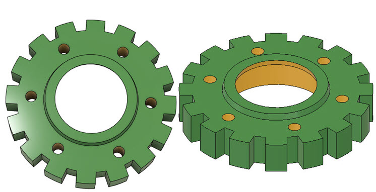
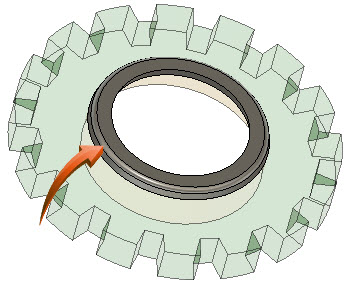
Square-Tooth Gear
modifying the gear
 Worksheet
 Design Brief
Design Integrity
This tutorial describes and demonstrates the ease with which sketches, bodies and features can be updated to perform modifications on existing designs. This process is referred to as Design Integrity and forms the basis of Parametric Design.
The concept of design integrity is observed in this tutorial, whereby associated parts and features maintain a spatial and logical relationship to each other, allowing changes made to one element to be consequentially cascaded to other associated elements.
Design integrity, when used as a foundational concept in design, allows downstream processes such as assembly of components, simulation of design and manufacturing standards to be maintained.
In this session, the design from the previous WorkSession segment will be modified.
 Tutorial
Modification of an Existing Design
Use your own design from the previous segment or download the sample here.
Edit Sketch


- The original sketch will be modified to create the new features of the inner extrusion and the holes which are formatted into a circular pattern.
- Use the ViewCube to set the view to Top.
- To isolate the sketch profile in the Canvas, hide the Bodies by checking the Hide icon next to Body1. The icon will be grayed out when hidden.
- Right-click onto Sketch1 in the Sketches folder and select Edit Sketch from the context menu. This isolates the sketch profiles in the Canvas, and turns the view to Top.
NOTE : All reference geometry in Sketch1 is accessible for updating or for creating new sketches without creating new planes.
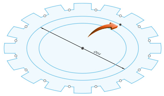
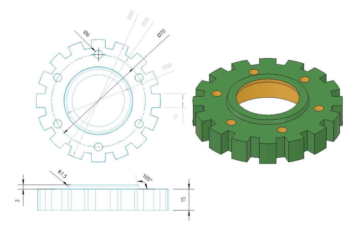
- Using the center of the circles, insert a new circle with a diameter of 64. Use Create > Circle Center Diameter to do this. The radius of the new circle is 64. This circle will be the PCD for the holes. This circle can be created as either a normal or construction element as it is not required for the final design.
- Select Finish Sketch to exit the Sketch mode in the Canvas.

Thin Extrude with Taper
Thin Extrude with Taper

Create > Extrusion
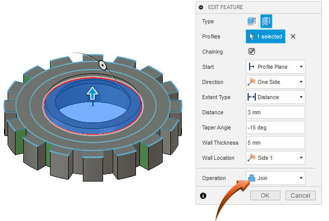
- A new feature will be added by creating a Thin Extrusion with a Taper Angle of the inner circle. A thin extrusion extrudes a profile by creating a wall thickness to a specific height.
- Select Create > Extrusion and select the inner circle. This can be done in any view.
- Select the Thin Extrude option shown below, then input the information as shown in the dialog box below.
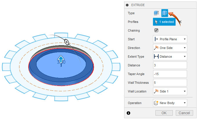
- The profile is extruded, creating a new body which is added to the Bodies folder of the Browser as Body2.
Fillet Edges

Modify > Fillet
This feature creates a transitional blend on the top outer edge shown below, to a radius of 1.5
- Select Modify > Fillet then select the top outer edge of the new extrusion, shown below.
- Input the information shown in the dialog box below to create a blended edge on the top outer profile.
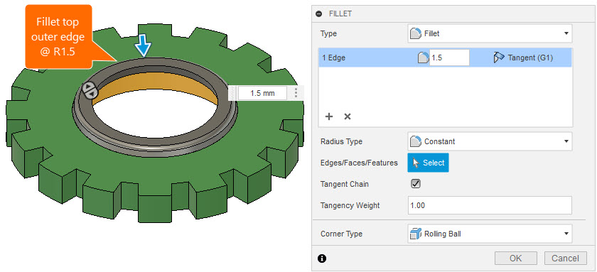
- The result is shown below.
Inserting a Point

(Edit Sketch) > Create > Point
A point is a sketch object which is usually inserted onto other sketch geometry to define the center of a hole. In this example, a point will be inserted onto the new circle so that a hole can be created using its intersecting geometry.
- Switch off Body1 and Body2 in the Browser.
- Right-click on Sketch1 and select Edit Sketch from the context menu.
- Select Create > Point, then insert the Point onto a quadrant point of the circle. This can be done from any viewpoint
- Select Finish Sketch after the Point is inserted.
- Use the Browser to show Body1 and Body2.
Creating the Holes

Create > Hole
Holes will be inserted onto the top face of the first extrusion. By creating the holes with a 'through imprint' the hole length will maintain its depth integrity if the extrusion is updated.
- Use the ViewCube to set the viewpoint to TOP.
- Select Create > Hole and select the top face of the first extrusion, shown below.
- Select the first Reference in the Hole dialog, then indicate the Point on the quadrant of the PCD.
- Input the data as shown in the dialog below, then drag the hole to the newly inserted Point found on the quadrant of the PCD, shown below.
NOTE : By providing a shape setting of All, the hole will extrude the entire length of the associated part, irrespective of the extrusion depth of the part.

- The result is shown below.

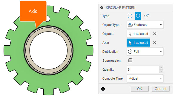
Circular Pattern

Create > Pattern > Circular Pattern
A circular pattern will be created of the newly created hole feature. This duplicates and distributes the feature around an axis. In this case, the center point of any of the concentric circles is used as the axis.
- Select Create > Pattern > Circular Pattern.
- Select the Features option in the Circular Pattern dialog, then select the newly created hole using the Timeline or by selecting the in-place feature. This can be done in any view.
- Input the data shown in the dialog box below to create the circular pattern.
- The result is shown below. This feature has been added to the Timeline and can be modified by right-clicking onto the feature and selecting Edit Feature from the context menu.
Updating the Extrusion

The extrusion of Body1 can be updated to a new depth. The hole was created with a Shape Setting of Extents - All, which will automatically update the 'through imprint' of the hole to accommodate the new depth.
- Use the Timeline to select the first extrusion of Body1. Right-click on the Extrude icon and select Edit Feature from the context menu.
- Create a new distance of -15 to increase the depth of the extrusion, shown below.
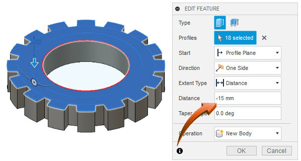
- As can be observed from the image below, the holes have consequentially updated to accommodate the new depth of the extrusion.
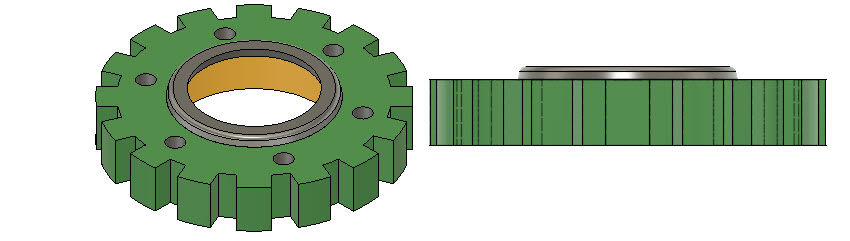
Combining the Parts

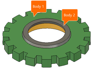
At this stage, the 2 extrusions are separate bodies, as shown in the Browser, below.
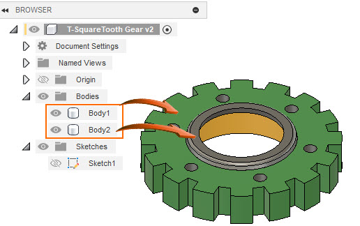
By modifying the smaller (Body2) extrusion to Join it to the associated part, the bodies of the two extrusions will be combined into a single part.
- Right-click on the extrusion in the Timeline, shown below, then select Edit Feature from the context menu.
- Update the Operation data to Join, shown in the dialog box below right.
- After this modification, the bodies in the Browser are combined into a single Body.
NOTE : The extrusion feature is still available in the Timeline as a separate Feature and can therefore be modified at any future stage of the design.
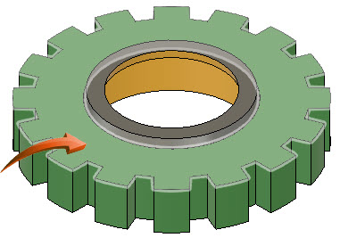
Appearance

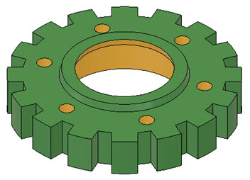
The exterior and interior faces of the new extrusion and the holes can be adjusted to be consistent with the interior face of the first extrusion.
- Right-click in the Canvas and select Appearance from the context menu.
- Drag the preferred material onto the body, feature or face so that the result is similar to the illustration below.
 sandbox
- Use the Timeline to modify the features of the part. In the example below, the hole diameters have been updated to 8 and the circular pattern is reduced from 6 to 4.
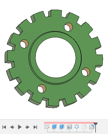
- To modify original sketch profiles, right-click on the Sketch in the Sketches folder in the browser and select Edit Sketch to modify original sketches.
- To add new elements, a new sketch profile can be added by selecting the Sketches folder then selecting Create > Create Sketch from the ribbon menu.
 Summary
- The concept of design integrity ensures that features cannot be modified to a state which would compromise the associated and interdependent features.
- The ability to update a design is dependent upon the design preparation of the original part. Sketches, bodies and features should be well organized in both the Browser and the Timeline.
- When features are updated to Join other features, the body of the modified part will be incorporated into the main part. When parts are combined, they are merged into a single body, but their independent features are retained in the Timeline.
- When extrusions or holes are created with a 'through imprint' the feature will retain its relationship to the top and bottom faces, irrespective of the height/depth of the object through which they travel.